Calibration and Installation
Safety Warnings:
1. To continue with this build sequence, access to 230V mains voltage is required. Please take great care, and do not undertake this activity unless you feel confident to do so.
2. Before installing a 'MK2' control system, the associated immersion heater and thermostat should be checked to ensure that they are in good working order. After years of infrequent use, these peripheral components may need to be replaced.
Calibration
When running in its "normal" mode, the Mk2 PV Router can reliably divert surplus power without need for any calibration. However, to provide an accurate indication of diverted power, and to operate correctly in anti-flicker mode, the system needs to be calibrated.
A simple approach to calibration is described on this page. For more accurate results, the user's electricity meter can be used as a reference standard. That alternative technique is described on the Improved Calibration section of this Build Guide.
A simple way to calibrate the two measurement channels is to clip each of the CTs around a test lead through which a known amount of mains power is flowing. If CT2 has already been built into the internal wiring, a test current can made to flow through that path by means of the override switch.
Calibration can be conveniently performed using the sketch
NB. For this sketch to run, the TimerOne library needs to be installed within the Arduino IDE. A zipped copy of this folder is available on the Downloads page.
As with most of the sketches for this board, the code needs to be configured for whichever version of the hardware it is running on. This involves a one-line change near the start of the code. If ICs 3 & 4 are in use, the line
#define PIN_SAVING_HARDWARE
needs to be included; otherwise, this line needs to be commented out (by adding "//" at the start of the line).
The sketch cal_bothDisplays_n.ino measures the real power that is flowing through the two current sensing circuits. CT1 and CT2 are intended to be used for the "grid power" and "diverted power" respectively. One set of results is presented at the 4-digit display and also at the Serial Monitor; the other set is discarded.
The "mode" connector is used to select which channel's data is to be displayed. If the two pins at the mode connector are shorted together (usually by means of the "operating mode" switch), the displayed values are from CT2; otherwise, they are from CT1.
The values for powerCal_grid and powerCal_diverted need to be adjusted until the displayed values for power are similar to the actual power that is believed to be flowing. Those calibration values can then be transferred into the Mk2 Router sketch. The calibration values for each individual system will depend on the operating voltage and the burden resistor values. For a 3.3V system with 150R burden resistors which has an operating range of approx 4 kW, the calibration values will be around 0.045. For a less sensitive system with a greater operating range, the calfactors may be as high as 0.12.
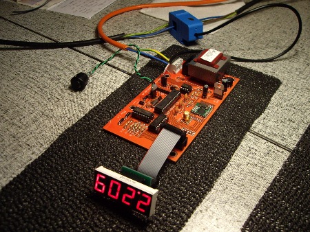
Here, I am checking the calibration for CT2.
NB. The CT2 channel would normally have a bobbin-type CT rather than a clip-on one.
Various points in the above photo are worthy of note:
- To get the values for CT2 to be displayed, rather than those for CT1, I've plugged an external switch onto the 2-pin "mode" connector. This switch is in the closed state. If I were to open the switch, the displayed value would return to 0.000 because there is no sensor at the CT1 port.
- The displayed value of 2.209 kW is rather high for my 2 kW heater. That's because I'm using the default value of 0.05 for powerCal_diverted. For this board, and all similar ones that I've assembled to date, the correct value is closer to 0.045. This change in cal value would cause the displayed value to be reduced to nine tenths of the value seen here, i.e. 1.988 kW.
- The board that I'm testing has the extra pair of logic chips (ICs 3 & 4). The calibration sketch must therefore include the "#define PIN_SAVING_HARDWARE" statement. If those two ICs were absent, the #define statement would need to be commented out.
- The 4-digit display will only appear the right way up if the the main board is orientated with the ribbon cable outlet at its top. In all other orientations, the ribbon cable will need to include an appropriate bend.
- Not shown in the photo, but if the measured power is negative, alternate values are suppressed. This gives a flashing appearance at the display. Every value, however, can be seen at the Serial monitor along with a '-' sign when appropriate.
[I find it hard to believe that the "4543" 7-segment driver IC can't provide a '-' symbol!]
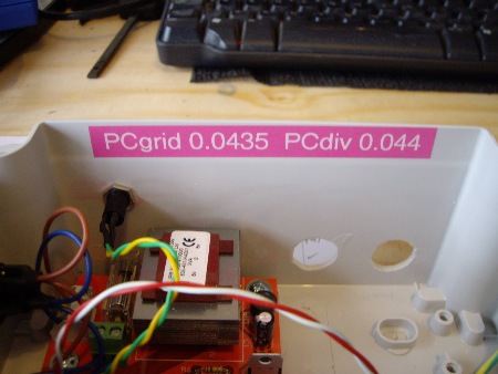
This pretty pink tape came as a freebie with the standard black & white tape that I normally use!
Having calibrated the system, the relevant powerCal values can be transferred into the appropriate Mk2 Router sketch. Several versions of the Mk2 PV Router sketch are now available via the Downloads page.
NB. For all my "Mk2" sketches, the TimerOne library needs to be installed within the Arduino IDE. For RF-equipped sketches, the JeeLib library will need to be installed too. For the latest RFdatalog sketch, which measures temperature, the OneWire library is also needed. Zipped copies of these library folders are available on the Downloads page.
Installation
On the Downloads page, there is an Installation Guide for pre-built systems that I have supplied. That document should be equally applicable for any system which has been assembled according to this Build Guide.
Having ensured that the system behaves correctly on the bench, it is ready to be connected into the fixed wiring of the premises. Connection details are are provided in this wiring diagram.
Providing that the Router has been assembled according to the above diagram, it should be capable of passing the standard electrical tests for Continuity and Insulation Resistance. While these verification activities are in progress, it is important that the two 240V AC switches are set correctly, i.e. mains switch 'off', override switch 'on'. There's more about this in the Assembly and Final Test section.
Section 8 of my Diverting Surplus PV Power article provides a wiring schematic for an installed Mk2 Router system. Although that article was written in the context of an Arduino Uno, the principle of operation has not changed. An updated version of that diagram is shown below, and a PDF is available here
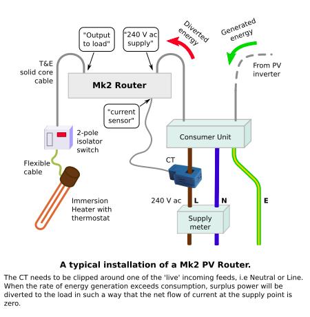
- - a permanently live supply from the Consumer Unit or fusebox;
- - a switched output to the load, which is usually an immersion heater;
- - the external CT which is clipped around either of the 'live' tails.
After fitting the external cables, the tightness of all electrical connections should be rechecked. Loose connections on power wiring can lead to arcing and overheating. Re-checking the tightness of all power wiring after a few weeks of use would be a wise precaution.
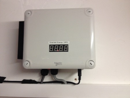
This photo was taken before PV generation had started for the day, so the display was still in its 'idle' mode.
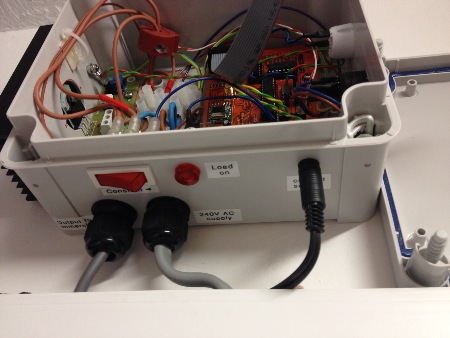
From left to right:
Switched output to the immersion
Permanently live 230V AC supply
current sensor (CT1)
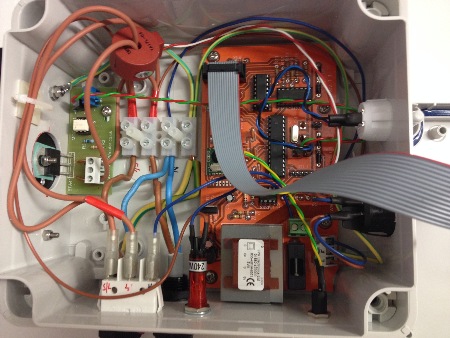
For the above installation, the existing cable from the immersion was rather short. I would normally have left more slack within the enclosure.
Each pair of Neutral and Earth wires share a single connector. These wires should be adjusted into the correct position (i.e. side-by-side) before the screw is tightened.
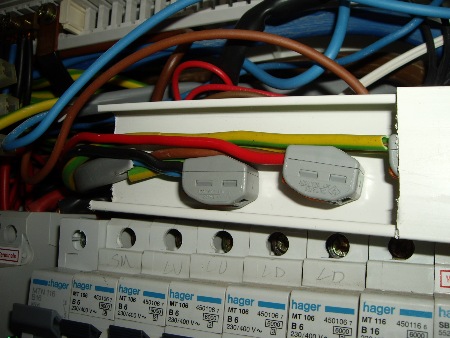
Here, each pair of cores were joined using 2-way Wago connectors and placed inside a short length of conduit for protection.
Two different sets of cable colours are in use for this installation.
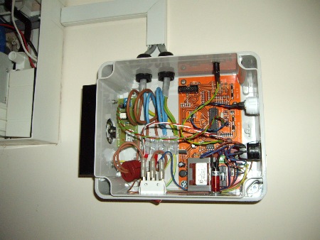
With the extended wiring in place, plenty of slack was available for the power cables at the adjacent router.
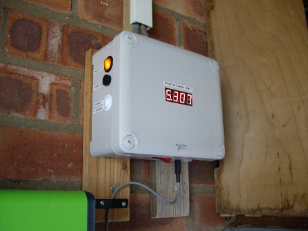
When I first assembled this guide, my own system at home was still based on an emonTx.
From the outside, it appears and operates just as described in this Build Guide.
In the welcome Spring sunshine, our DHW tank reached its max temp today.
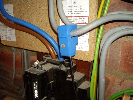
The state of our Neutral cable suggests that this particular sensor has been moved around quite a few times!
For correct operation, the external CT must be the correct way around. If it is attached with the wrong orientation, the feedback in the system will be positive rather than negative. Once activitated, the load would then remain firmly 'on' which would be no good for daytime use.
This incorrect configuration, however, can be very useful for after-hours checks. By reversing the direction of CT1, the load should soon come on and stay on. Then, when CT1 is returned to its correct orientation, the load should go off. Having demonstrated this behaviour, you can feel confident that the system will operate correctly whenever genuine surplus power next becomes available. A video showing this principle using prototype hardware can be seen at:
https://www.youtube.com/watch?v=oF8HACCsK4M
The Router regulates the energy that is consumed by the load by turning its power on or off at appropriate moments. Two settings are provided, known as Normal and Anti-Flicker. A video showing an installed system operating with each of these settings can be seen at:
https://youtu.be/WU141Ou7Kcc
For general use, anti-flicker mode (AF) is recommended. By setting the AF limits as wide as the supply meter will allow, any conducted disturbance to the mains supply will be minimised. A video showing the tolerance of an electricity meter to the reverse flow of energy can be seen at:
https://www.youtube.com/watch?v=7lM0muV_RQY
In conditions where only minimal surplus power is available, bursts of power will be supplied to the load very infrequently when running in AF mode. Visual activity can be increased by switching from "AF" to "normal" mode. Both modes are equally effective at diverting whatever surplus power is available.
Please note that, to comply with the IET Wiring Regulations, the installed system should be verified by a "competent person" (BS 7671, 17th Ed., para 610.5).
Also, because the conditions of use are beyond my control, I am unable to accept any responsibility for the use of equipment that is described on this website.
Thank you for sharing this journey. I wish you every success with your Mk2 PV Router project.
Robin Emley