Photo Gallery
This page is for any photos that may be of general interest. As well as standard Mk2 units, there is plenty of other activity going on behind the scenes. Many of the systems that I build are 'specials' as agreed with the customer.
If you're interested in anything that you've seen here, or you have a suggestion for another way of doing something, do drop me a line.
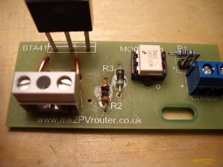
The pre-tested triac and PCB can be soldered together at later time when their mechanical 'fit' is known.
Without the triac in place, this board can be posted as a "Large Letter" 😀
Otherwise it's a "Small Parcel" 😟
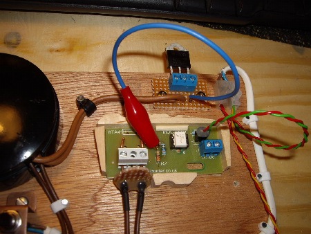
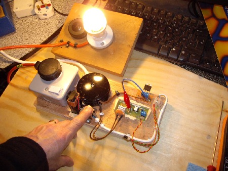
The 'gate' signal for the triac is connected to the upper end of R2 by a flying wire.
To aid this process, I leave this leg slightly raised on any output boards that are to be tested in this way.
It is vital that all of the triac's connections are sound, otherwise …
The series resistors don't like this treatment and expire very rapidly.
This is one board I won't be offering to anyone!
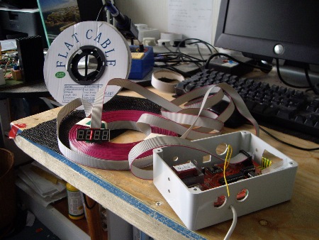
Users of Mk2 Routers have extended their CT and output cables by several tens of metres without any problems.
Here, the display has been connected via 100 feet of ribbon cable, and it's working perfectly.
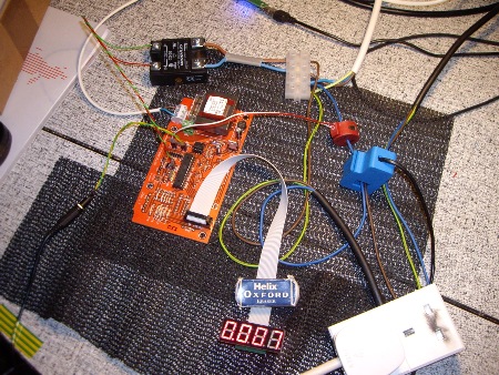
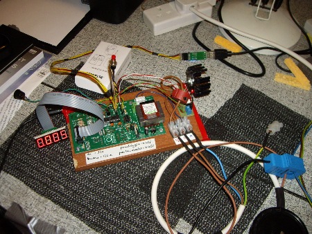
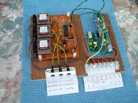
A simple heatsink which is shared between the three triacs will allow initial testing to take place on site.
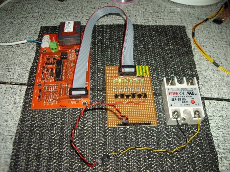
All the data and power lines have been routed via a standard ribbon cable.
This approach allows the 3.3V RF module to be fitted at a later stage if required.
This system is also now in Australia.
NB. The later (green) PCB can support both 5V SSR(s) and the 3.3V RF module without requiring any off-board components.
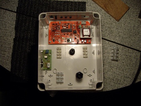
A larger enclosure has been used to ensure plenty of space.
Because the 4-digit display was not needed, that area of the PCB has been modified to provide extra connections.
NB. This system (above and below) was assembled before the new (green) PCB became available. When using the later PCB, connection points for additional loads are available without the need for any modifications.
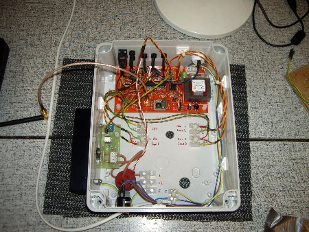
The CAT5 and power cables appear through the rear of the enclosure which provides a neat finished appearance.
Each of the remote loads has a local LED (the red/yellow wires) to show when the load is active.
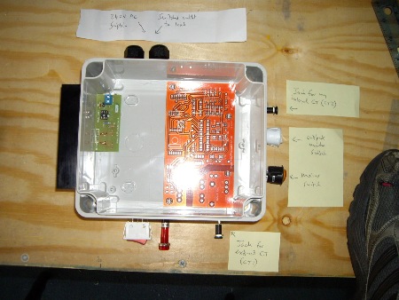
The Mk2 system that is being planned here will not have a display.
Instead, the CT which monitors the diverted power will be connected to an adjacent emonTx. The data can then be sent to the user's emonBase.
The inter-unit cable is a standard 3.5mm M-M coax lead.
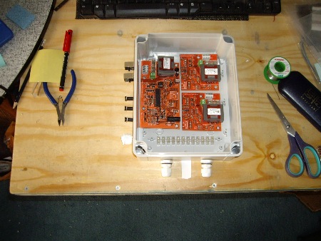
The two smaller boards just provide the V and I sensors for L2 and L3.
My 3-phase PCB is more compact and simpler to assemble, with no need for any inter-connecting cables
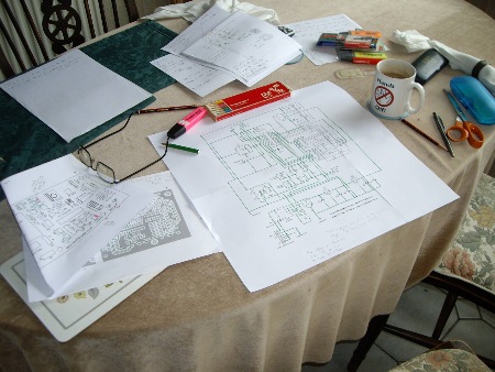
Checking the layout for my new "main" PCB.
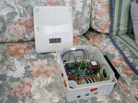
To minimise its overall width, this system has been assembled in 'portrait orientation.
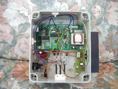
The main board has been moved sideways a few mm to allow clearance for the heatsink screw.
One corner of the output board has been filed away to allow more room between the two boards.
This system (above and below) is configured to drive multiple outputs. By fitting the pin-saving hardware (IC3 & IC4), the five pins which are normally used for the RF module are directly available for this purpose.
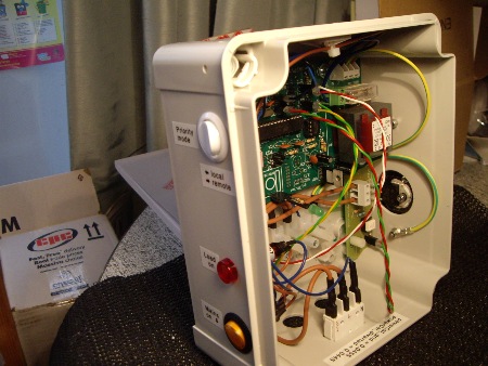
With the multiLoad Mk2 sketch, the external switch is used to determine the load priorities.
This switch selects between the normal output (at the "trigger" port) and physical load 1.
In this photo, an LED + series resistor can be seen at the "physical load 1" port (at D12 in the RFM12B area).
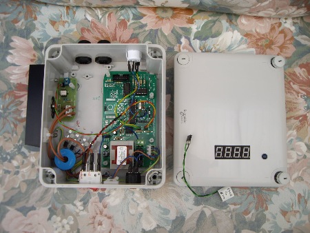
In the system shown above, the main PCB is attached using the standard mounting points.
Another option for a potrait layout is to rotate the PCB within the box as shown here.
In the photo below, I am testing the operation of the sketch Mk2_withRemoteLoad_4.ino before release.
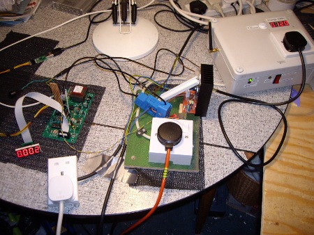
The board on which the sketch is running is on the left …
the output stage for the 'local' load is at the centre …
and the RF-linked output stage for the 'remote' load is on the right.
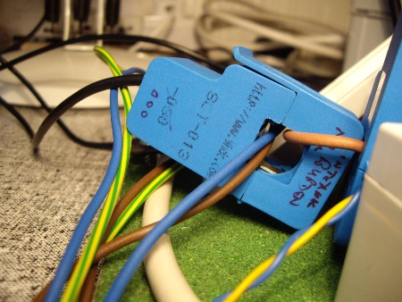
To provide a realistic test environment, both output stages are wired through CT1.
CT1 encloses the Neutral (blue) core of the PV simulation circuit, and also the Live (brown) core of each of the output stages.
This particular CT started life with an internal burden resistor, but it has since been removed.
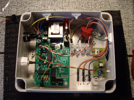
At first glance, this Router looks much the same as many others that I've built.
But this board has an extra feature …
Because this system does not include the RF module, one of the spare IO ports is being used to measure temperature. The photo below shows how the three connections for the Dallas sensor have been made. These connections are: any IO port with a 4K7 pullup resistor to Vcc; ground; and Vcc.
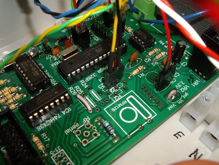
Vcc is accessed at one of the C9 pads, a (pink) 0.1" wire link being required at the VR2 point.
The pull-up resistor should be 4K7 rather than 3K9 as shown here (at side of the RFM12B zone).
The sketch Mk2_RFdatalog4.ino includes the measurement of temperature for datalogging purposes. The ability to measure temperature could also be used to provide an automatic top-up facility for a water tank if insufficient surplus energy is available.
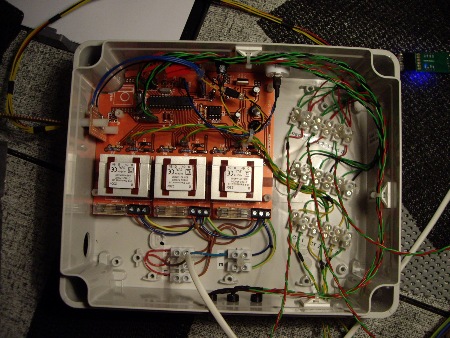
As requested by the customer, the CTs are connected by screw terminals rather than jack-sockets
Because the RF capability is not required, up to six (wired) remote loads can be independently controlled by this system.
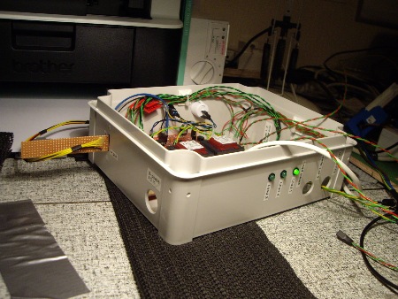
This system has LEDs to show when any of the first three loads are active.
By means of an extra cable, the Serial Interface can be accessed from outside the box.
This cable also includes a reset button (yellow/black wire).
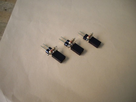
By mounting the burden resistors on DIY adapters like these, the scaling of the current sensors can be easily changed.
These adaptors, with their 220R burdens, are for use with a set of larger CTs.
With this setup, the working range for each phase is approx 10 kW.
For the system below, a simple internal aerial has been made from a standard SMA extender cable. In this case, the SMA socket is nearer to the top of the box so it makes sense for the aerial to run downwards from the socket rather than upwards. This type of aerial will work equally well in either orientation. According to Wikipedia, it is a quarter-wave monopole.
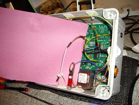
This system uses 868 MHz for which the 1/4 wave aerial length is 82 mm.
For a 433 MHz system, the 164mm aerial would probably need to protrude outside the box.
data source for aerial lengths
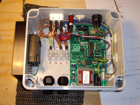
In this system, a Crydom SSR has been used instead of the triac-based output stage.
By including the pin-saving hardware, 5 spare IO ports are available.
Each of those IO ports has been fitted with a pair of pins. Their locations are given in a table near the top of the Port Options page.
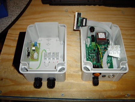
For this system, which is not yet in a completed state, the base unit and output stage are in separate enclosures.
The low-power mains cable for the base unit is terminated on a raised bracket for ease of access.
The linking cable will be connected via audio DIN plugs.
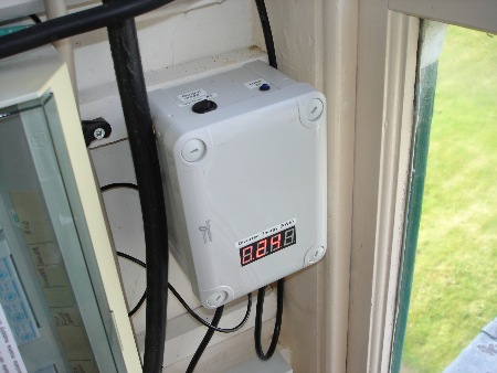
The 4-core cable between the two units carries two independent signals:
- the 'downstream' control signal that is generated by the main unit;
- the 'upstream' signal from the CT in the remote unit which monitors the diverted energy.
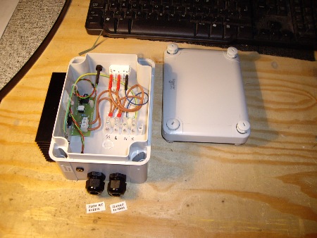
There is an LED to show when the load is on, and also a mechanical override switch.
Because there is no need for a secondary CT, the 2-core control cable is connected via a mono jack-socket.
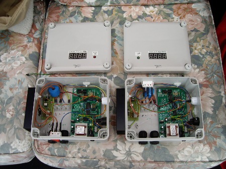
Although these two systems are very similar, the location of the override switch makes a significant difference to the layout of the mains wiring.
Instead of the neon, each of these systems has an LED in the lid. The cable plugs onto a pair of pins at the top of the RFM12B area (for access to D12).
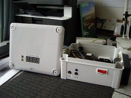
The optical sensor is polled every mains cycle so is capable of detecting pulses from an electric meter.
There is also a switch (not visible here) to enable or disable an automatic top-up facility.
For the system shown above and below, all of the IO ports have been used.
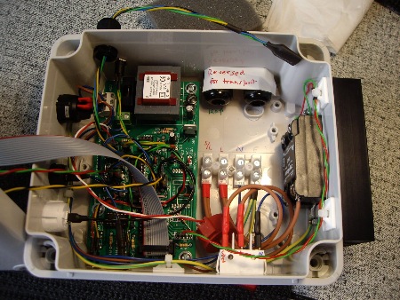
The two LEDs on the front panel are plugged directly onto the PCB. Their cables are below the ribbon cable.
By means of a simple extension cable, the serial port can be accessed from outside the box.
The cable glands have been reversed for transport.
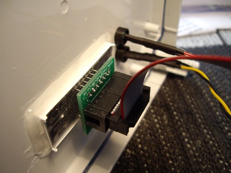
For this same system, the adapter plate has been soldered directly to the pins of the display module.
This arrangement is described in more detail on the "Display PCB" page.
The ribbon cable can still be uplugged from the boxed header into which the IDC termination fits.
Some new features on a recently built system (June 2015):
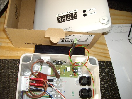
Red heat-shrink sleeving for the 230V Line terminals
Heat-resistant sleeving for any wire that's near the triac
A "load on" LED in the lid is connected via the SIL pins on the output board
and one from July 2015:
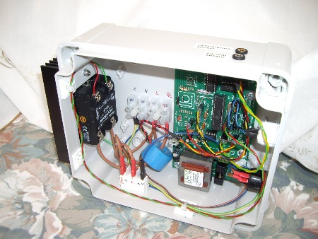
Although this system runs at 5V, a 6V transformer is fine. To maintain the size of the voltage waveform, R4 is 18K rather than 10K.
The temperature sensor is again at D10, via R23, this time with the correct value of pullup (4K7).
A lid-mounted "load on" LED is driven from D12, at the top of the RFM12B area.
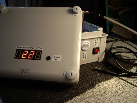
The above system has an extra control feature.
When the red button is pushed, the most recent value from the temperature sensor is shown at the display.
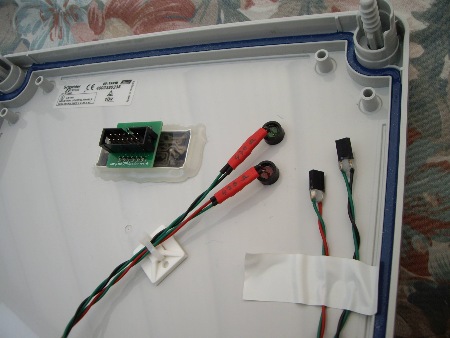
Although not for the same system, the cables for these lid-mounted LEDs have been clipped to the underside of the lid.
The other end of these two cables go onto the SIL pins of the output boards to show when each of the loads is "on".
The next four photos are for a 3-enclosure fully wired system. Because the behaviour of the supply meter was already known, this system can operate permanently in Anti-flicker mode. Hence there is no need for an "output mode" switch. Testing how the supply meter behaves in the presence of a burst-mode power diverter can be easily achieved by borrowing one on my Demo Units.
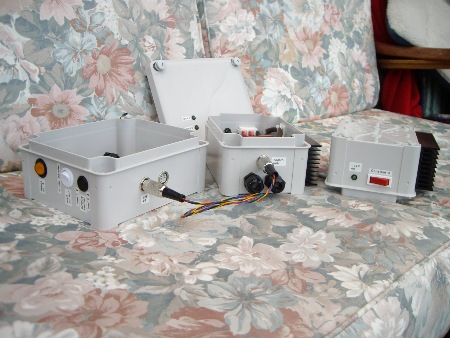
Two output stages are connected to the control unit by 4-core cables.
A pair of switches allow the loads to be operated singly with switchable priority, or in parallel.
One of the output stages has been rotated so that its upper face can be seen.
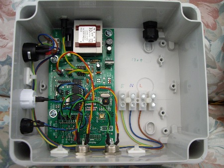
Although one side of this box looks rather empty, the other one is feature packed.
The two loads and their local LEDs are driven from four of the IO ports at IC3.
The pair of switches for selecting how the loads should be operated are at IC3 pin 7 (D5) and the "mode" port (D3).
A local load could still be fitted later.
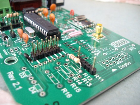
Each of the remote units has a CT which is linked via the control cable. The signal from load #2 is connected to port A3 at one end of R11.
The burden resistor is at R12 with its legs bent around under the board.
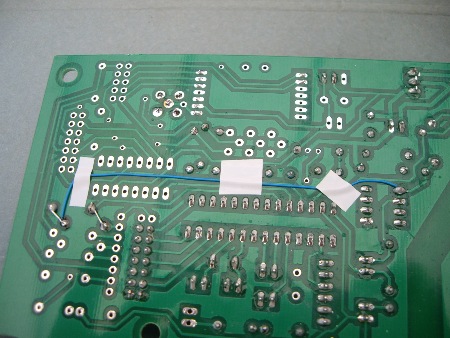
When using the R11 location as a third current sensor, the Vref signal must be extended to this point (blue wire).
The bent legs of the associated burden resistor, and the track that connects R11 to A0 (pin 23), can also be seen.
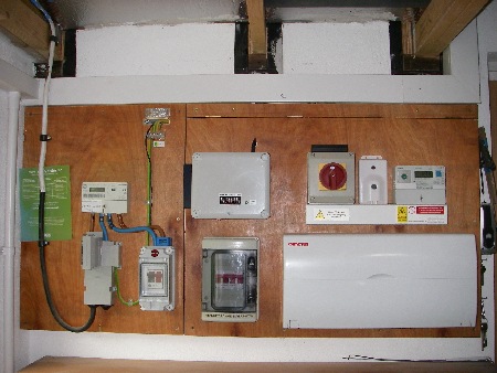
The power cables for this system come through the back of the enclosure thus giving a very tidy appearance.
The black cable at the top of the Mk2 box is for the CT, and there is a socket for a temperature sensor immediately behind it.
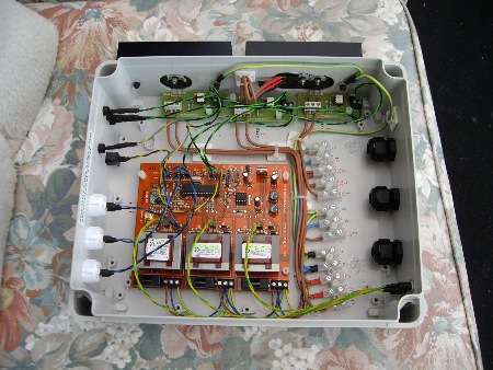
All of the IO ports are in use, each being associated with a 0V pin.
Two of the three output stages share a single heatsink (close-up view).
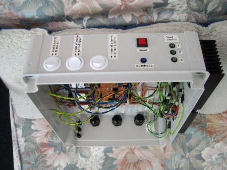
The top surface of this enclosure has three switches:
The one on the left disables all of the loads. The other two are for standard purposes.
There is also a 'watchdog' LED which pulses every two seconds.
The Rev 2 3-phase PCB also supports a reset button.
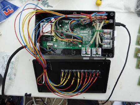
For consistency, all of the control signals are active-low. The active-high signal from the "trigger" port is not used.
The square boxes are RJ45 connectors for the control lines.
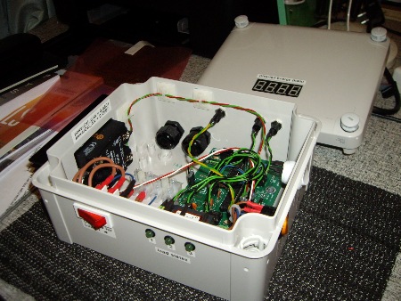
Two additional output stages can be controlled via jack-sockets at the upper right.
On the lower edge, an LED shows the state of each load.
The mechanical override switch is only for the local load.
For the system in the next two photos, a 3-phase PCB has been squeezed into a standard sized enclosure.
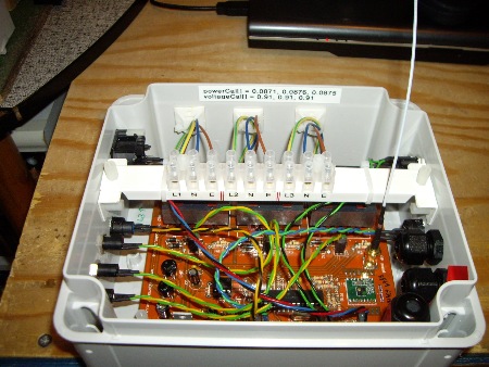
To save space, the power connectors for 3 x (L, N & E) are fixed to a bar at the top of the box.
Pity that I messed up the label. It should have been fitted to the other side of the bar 🙁
The dark component at the upper left is an RJ45 socket for an optical sensor.
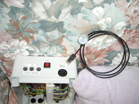
This type of optical sensor can be supplied by the Open Energy Monitor shop.
Its three wires require connections to Vcc, Ground and any of the IO lines.
I can supply software for monitoring this sensor by polling.
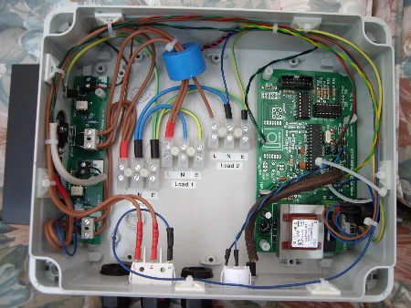
When two output stages are to be fitted in the same enclosure, a slightly larger enclosure can greatly ease the layout.
The extra space here has allowed a separate connector strip to be fitted for each of the power cables.
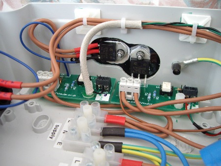
When only one load will be on at once, it makes sense for both triacs to share the same heatsink.
The small brown wire supplies power to the processor board. This avoids having four wires at the Line terminal when there are two output stages and an override switch.
The next pair of photos are for a bespoke system which uses many of my standard components. It's for controlling the heating of Domestic Hot Water in a house with an Economy 7 tariff. By means of dedicated wiring, storage radiators are only supplied with power during off-peak periods, but the DHW heater is fed from a supply that is permanently live. Using a pair of RF-linked boxes, the DHW heater is now only activated during periods of cheap power. Previously, a timer did a similar job but its setting was always problematic, particularly when the "hour" changed.
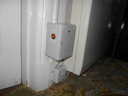
Whenever power is available, it transmits the integer 42 every second.
A blue LED on the front panel gives a short pulse when each RF signal occurs.
At night, it looks as if an emergency vehicle has just appeared on the scene!
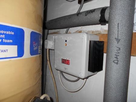
Whenever "42" is received, the output stage is activated for the next 3 seconds.
Consumed energy is monitored and displayed on the front panel. To heat this entire tank took 11.30 kWh.
Code for this project is available on request.
∗ ∗ ∗ ∗ ∗
Here are some photos of my Mk2 kits and boards that have been built by customers:
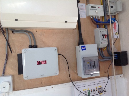
This next photo is from New Zealand where the power supply for heating the hot-water tank can be interrupted by the utility company at any time via a "ripple relay". To avoid the router being isolated on such occasions, a low-power feed from a wall socket has been used to provide a permanent supply for the router's control circuitry.
During periods of surplus power, energy from the interruptable supply is diverted to the hot water tank by the Router's output stage. This cable carries Line, Switched Line and Earth, hence only a single high-power cable can be seen.
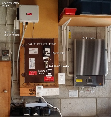
By means of a "cooker" connector, the high-power wiring for the immersion heater can be easily returned to a standard configuration.
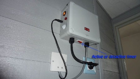
The switch at the bottom allows the hot water tank to be topped up using cheap overnight electricity.
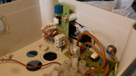
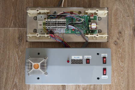
For this system in Denmark, I just supplied the PCBs and a few of the main components.
It's always interesting to see what can be achieved with a bit of ingenuity.
The triac for the output stage is under the expensive looking heatsink.
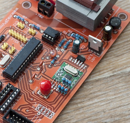
Note the three pairs of resistors which reduce the signal levels from 5V to 3.3V, circuit details are here.
These original PCBs are available for the cost of postage. Let me know if you would like one to experiment with 🙂
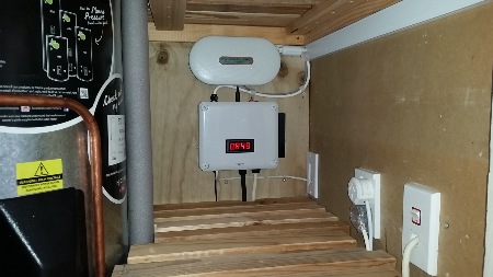
This Mk2 system is quietly diverting surplus power in New Zealand where a commercial equivalent would cost in the region of NZ$700.
More recently, this system has had an interesting upgrade, as shown below. The underlying Mk2 Router structure has not changed, but a Raspberry Pi Zero has been fitted above the main board to intercept data from the Serial port. The data is reformatted using a Python script, and sent via a Wi-Fi dongle to a broadband router. The data is forwarded to a conventional datalogging website where it can be viewed at any time. The live data for this system is at:
http://pvoutput.org/intraday.jsp?id=49355&sid=34477
NB. The generated power and ambient temperature graphs that can be viewed for this location (June 2016) are not sourced by the Mk2 Router. But "Mk2" contributions for Diverted Energy and Cylinder Temperature are soon to be included …
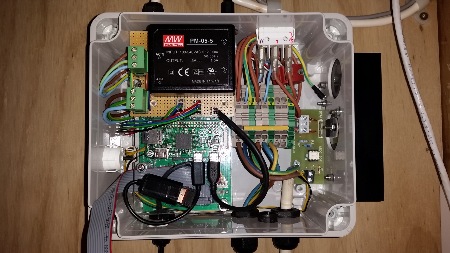
The large black box is a switched-mode power supply for the Raspberry Pi Zero.
A DIN-rail alternative to terminal block has been used for the power cables.
The next pair of photos are for an RF-linked system. The output stage in the base unit is used for heating domestic hot water. The remote unit supplies heating for an adjacent room.
The sketch for the base unit is: Mk2_withRemote_load_n
The one for the remote unit is: remote_Mk2_receiver_n
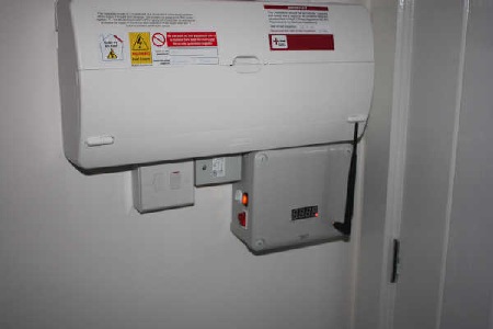
This is the base unit. By locating the aerial in the lid, complications with nearby components have been avoided.
The extension cable for the aerial can be unscrewed from the SMA receptacle on the PCB in a few seconds.
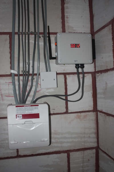
And this is the remote unit
By including an extra CT, the amount of locally diverted energy can be displayed here.
The base-unit includes support for a switch so that the priorities of the two loads can be swapped over.
By default, the remote unit will only get the opportunity to consume any power when the DHW tank is up to temperature and its thermostat has opened.
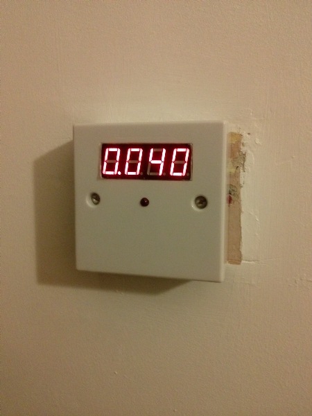
An extra LED shows when the load is active. This signal can be taken directly from the low-voltage side of the output stage PCB.
The enclosure is a standard surface-mounting box, as used for 13A mains sockets, with a blanking plate.
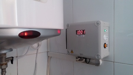

In this standard system by a UK customer, a firmly attached piece of conduit tubing has been used for both power cables.
larger image showing more of the power connections.
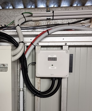
This tidy 1-load system is in Victoria, Australia. The photo must have been taken before the solar day had started.
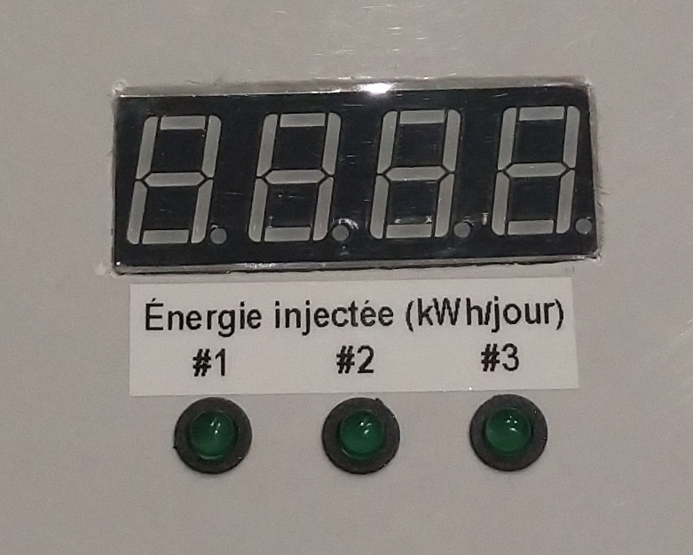
In the lid of the box, there is an LED to show the state of each load.
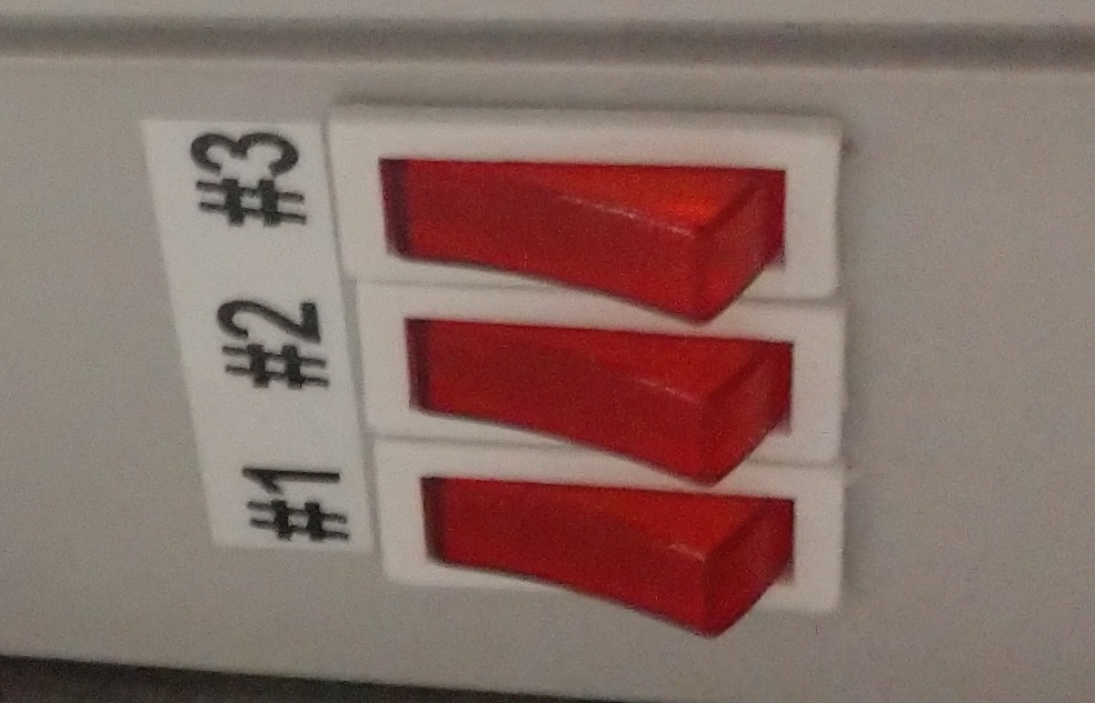
Each load has a seperate override switch
pour quand le soleil ne brille pas.
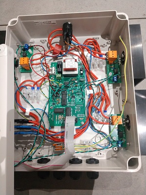
Inside the box, most of the power cable is 2.5 mm2 CSA, and some different connectors have been used.
It includes some novel features:
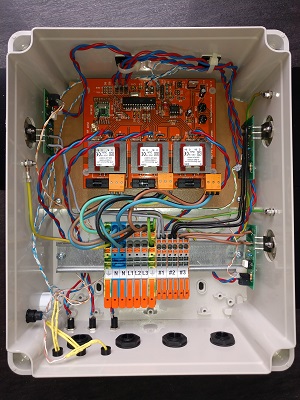
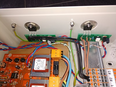
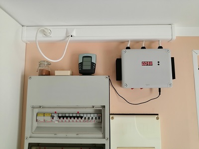
The next two photos show a 1-phase system for 2 x 3kW loads that has been assembled by a constructor in France.
It uses the Schneider NSYTBS24198 box and has two heatsinks.
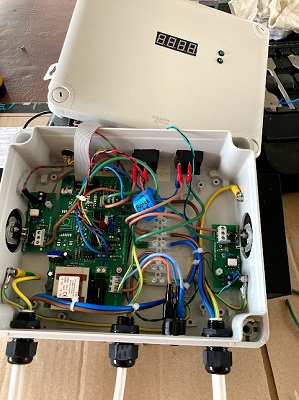
... and here is the inside view.
When using the larger box, there is plenty of room for the extra power connectors.
Each of the loads has its own override switch. Because those wires do not go through CT2, the display of Diverted Energy will only record surplus power that is supplied via the triacs.
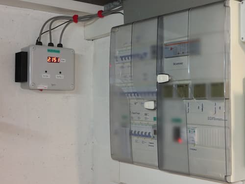
A neat 2-load system in France (for max 3kW of surplus power).
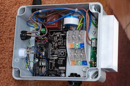
And here, with great attention to detail, is a similar 2-load system from a constructor in England. I particularly like the 3D-printed structure for the two tiers of power connectors, and the matching labels for the wire colours.
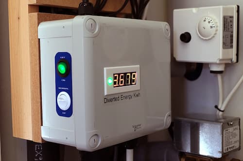
With its 3D-printed bezel for the display and smart labels, this one looks impressive on the outside too :)
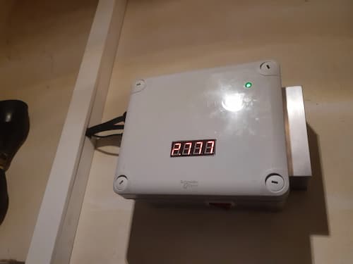
Here is another tidy 1-load installation in France.
It appears that the camera was too fast to catch all segments in the display.
As with the last system, this one has the heatsink in "mill finish" rather than black anodised.