Building the Display Assembly
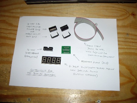
NB. Since this website was started, the design of the display assembly has been improved and simplified. The following photo shows a complete set of components for the display assembly in its current form. An equivalent image, showing the original version, can be found near the end of this page.
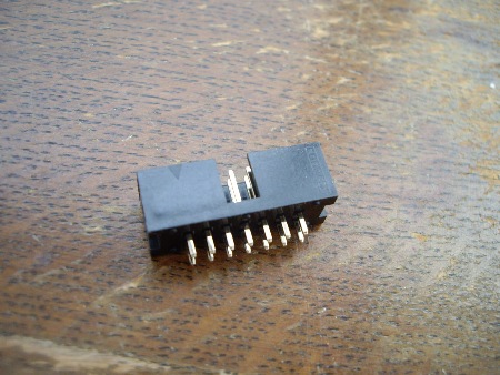
This component has a triangular identification mark which can be seen here at the top-left.
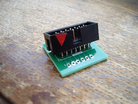
When correctly located, this component can be soldered into place. Only 12 of its 14 pins are used.
To make the identification triangle more visible, it has been highlighted with red tape.
When the boxed header has been soldered into place, the adapter plate can be fitted to the display module. Strips of card can be used to create extra space between these components. Later, when the display module is being glued into the lid of the box, it will be easier if the adapter plate is not tight up against it.
NB. The orientatation of the display module relative to the adapter plate is important. Although not visible in the photo below, the decimal points on the face of the display module are closest to the camera.
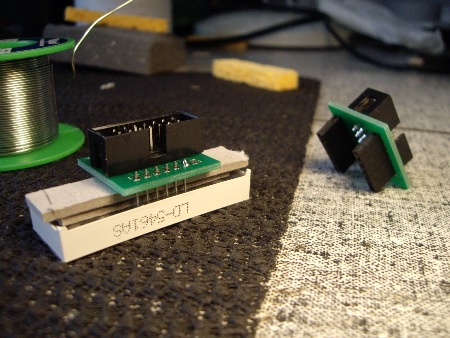
Solder has been applied to just one of the pins. After checking the 'fit', the remaining 11 pins can be attached.
NB. The adapter in the background is of the original type.
A 14-way ribbon-cable is required to run between the adapter plate and the main PCB. Most ribbon cable has a red mark along one edge, and this should be aligned with the triangular mark on the connector at either end.
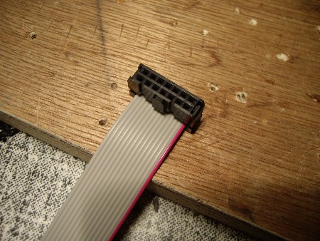
…it is inserted into the connector from the opposite direction.
This sub-assembly is then compressed in a vice or similar until the plastic tabs at either end 'click' into place.
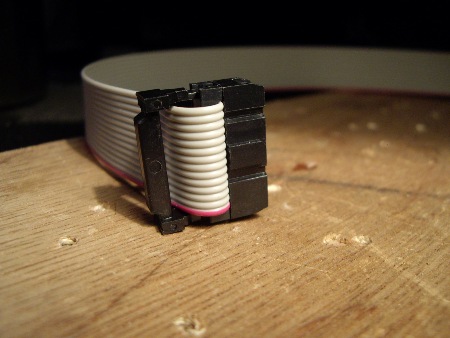
The strain-relief clip can be pushed into place by hand.
Here, the clip has not yet been pressed fully home.
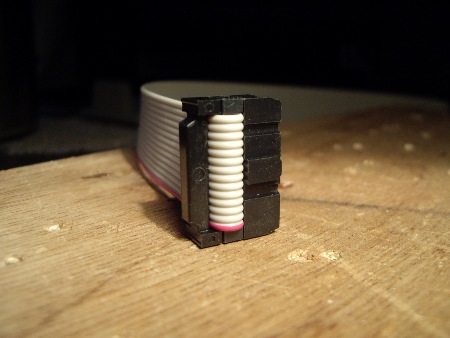
Although barely visible in these photos, the triangular mark on the body of the IDC connector is next to the red line of the cable.
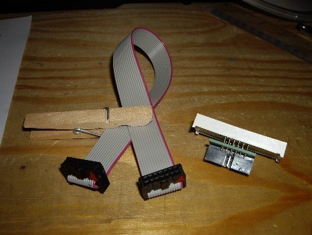
This ribbon cable assembly is now ready for use.
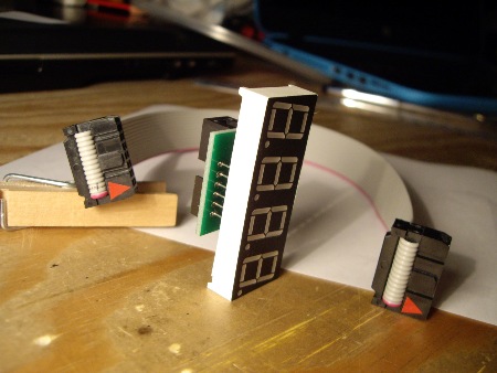
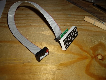
Testing the display assembly is described on the Assembly & Final Tests page.
∗ ∗ ∗
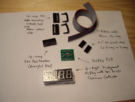
Two SIL-socket strips are required, and the PCB is slightly different.
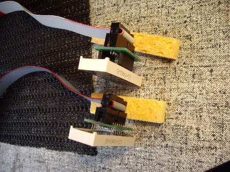
The upper one shows the original method with the removable adapter.
The lower one shows the new method in which the adapter plate is soldered directly to the pins of the display module.
Parts list for the display assembly:
| Identity on PCB | component description | # used | notes |
|---|---|---|---|
| display PCB | 1 | ||
| 4-digit display module with 12 pins | 1 | common cathode | |
| 14-way ribbon cable, 30mm | 1 | or longer for a larger box | |
| 14-way cable connector (IDC) | 2 | ||