Below is a basic diagram of my solar PV and electric setup and part of my intended OEM setup.
I have an InfiniSolar hybrid inverter that has a battery bank attached and solar PV panels and it has a load circuit and feed from utility power.
I have setup a separate new DB (about 2 meters above, in the loft/attic room, the main house DB) that is fed from the inverter's load circuit so that the attached devices (PC's, server, lights, entertainment center) would then be fed from the inverter connected battery bank during a power failure.
Any excess solar energy, not fed to the load circuit, or the trickle charge for the batteries, is fed back on the utility line. Most days now, if we're not running the air-cons, the utility meter turn backwards.
Apart from the CT's ,the emonTX will also have temp sensors, in my office, in my roof, one under each PV array (seeing as heat effects PV efficiency - very hot here in summer) and one outside (probably in a ventilated piece of electrical PVC conduit to raise it off the hot roof). Someday I'd like to add light meters on each PV array to measure the light level the arrays are receiving.
My 2 DB's are reasonably close to each other, just separated vertically, so I'd probably attach all the CTs within the DB's, instead of trying to extend CT3 to get closer to the inverter (very much oversized cable from the inverter to the new DB).
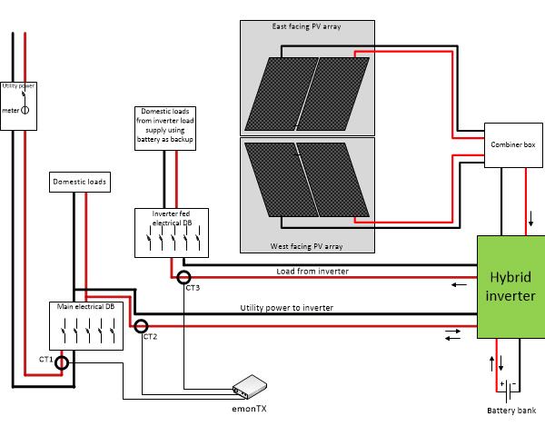
CT1 will monitor the main line from the utility.
CT2 will be on the cable from the utility (after the main DB earth leakage) to the inverter
CT3 will be on the load cable from the inverter
(I'll probably have an additional CT on my solar/electric immersion water heater line to get an idea of it's usage separately, mainly for the cooler winter months)
The solar PV setup documentation mentions 2 types of setup which I don't seem to fall into either, mainly because of the load circuit from my inverter.
They way I see it, my solar PV generation value would be the sum of my CT3 (inverter load) MINUS CT2 (utility<->inverter).
If the result is lower than the reading from CT3 then the panels are producing energy.
If the result is a positive number then my solar is producing less than the inverter load and if the result is a negative then the inverter is feeding the excess back on the utility line.
Would I be able to setup this simple equation in emonCMS to calculate the solar generation?
Is there anything wrong/incorrect about my intended setup as above?
Edit: I've found references to "virtual feeds" that sound like that might do what I need. Is that correct?
Please forgive the ignorance of this question...
Lets say that by chance my neighbour also installs an OEM system, would they be able to "highjack" my emonTX (other other transmitted devices) and prevent me from receiving my data or would they also just be able to receive my data but not effect my data collection or would my emonTX be "tied" to my emonBase once connected?
Thank you to all who read and respond to these annoying newbie questions, it helps a great deal in deciding on what kit I'll be ordering so I don't order too little or too much, especially with our shoddy exchange rate (currently about ZAR 24 to £1).
Rhys
Re: Hybrid inverter in the mix
I'm no emoncms expert, but I think it's quite simple to derive your nett inverter power because, in the input processing, you can do "+ input" or "- input" - that's a different input to the one you're working on. The only possible problem that I can see is whether the voltage is the same each side of the inverter - is its output voltage the same as the input voltage and exactly in phase with it? That's relevant as you must be measuring the voltage somewhere so that you have a measure of real power, which you need to determine the direction of power flow on CTs 1 & 2. If CT3 uses what is essentially a different supply, you can't use a voltage measured on the supply side of the inverter to get real power in the load side (CT3), you can only have an estimate of apparent power.
If your neighbour installs a similar system, then he will be able to gather data from your emonTx as you will from his, and if both happen to transmit at exactly the same instant, it's likely that each will block the other and neither of you will receive your respective messages, so you'll both miss the odd message occasionally as the two systems drift in and out of synchronism. You'll both need to use a different "nodeID" for your two emonTx's, so that you know whose is whose.
Re: Hybrid inverter in the mix
Hi Robert,
The inverter references and synchronises its load output to the utility power, when utility power is available so CT1 CT2 and CT3 all would have the same voltage and frequency.
If solar is providing power (in part or full) for the load then the output is still sync'd to the utility supply values as the utility feed is used as top-up if the solar is not providing enough power to fully supply the load. The provided software shows the utility voltage, which my mulitmeter agrees with on both the utility and load side of the inverter, while utility power is available.
When utility power is not available then the inverter runs from solar and/or battery and its AC output would then be the configured 230V and 50Hz.
If the solar is producing more than the load, then batteries would not be needed and CT2 would potentially see a negative current as the excess solar energy is fed back on the utility line (I can't find any documentation that states whether the inverter will still feed to the utility line when utility power is off).
I intended powering the AC-AC PSU from a power socket connected to the inverter load supply DB, thereby always being connected to a relevant AC supply.
One thing the "CT3 minus CT2" calculation would not take into account is the inverter's battery charge current when drawn from the solar, and therefore not really be a true reading of the solar generation, but I'm willing to have a marginally skewed solar generation value. The float charge current is typically 0.3A (at 54V DC) when keeping the batteries on float charge but of course that would be higher if the batteries had been used (utility off) and now needed to be charged.
If the batteries are being charged from utility power then that would just increase the reading on CT2.
I suppose I need to try set the calculated value of CT3 minus CT2 to also be a minimum of zero as if the PV is not generating power (at night etc) then CT2 reading would be the load (CT3) plus the float/full charge current giving a negative result for the supposed PV generation.
I would eventually like to get the inverter data to feed into emonCMS, which would potentially provide the PV values (DC though) and load and battery charge, but I haven't started looking into the RS232 or USB data (supports both) from the inverter yet. I'm currently only using the supplied GUI application (Windows) to see the inverter data. The application does support manual export of data to either PDF or Microsoft Excel formats, but not simple CSV.
Re: Hybrid inverter in the mix
I can't find any documentation that states whether the inverter will still feed to the utility line when utility power is off
It won't be allowed to do that. Grid-tied inverters have to go to great lengths to ensure they don't feed power back out to the grid when the grid has gone away, for fear of electrocuting the linesman trying to fix the grid fault. The inverters run anti-islanding algorithms so as not to be fooled into thinking the grid is still alive by all your neighbours' inverters.
Re: Hybrid inverter in the mix
Thanks dBC, I wasn't sure about how it would handle that but figured it would not feed back when utility power was not available.
I had wondered what would happen if it did feed back and we were running an air-con and the supplied current from the inverter was not enough to correctly power the appliances, didn't have good thoughts. I know motors, air-cons, fridges etc, would not be very happy.
Re: Hybrid inverter in the mix
I don't see any serious problems with that. You will probably need to budget for a programmer, as there may well be a small phase shift between the supply side and the load side of the inverter, and if there is you'll need to adjust the phase compensation for CT1 & CT2.
Re: Hybrid inverter in the mix
Hi Robert,
Thanks, I do actually have a programmer in my shopping cart with the rest of the kit,waiting to be ordered. Just waiting for our exchange rate to strengthen a little, it's currently about ZAR 24.50 to £1
I can't say I know what you're talking about regarding "phase shift" but I guess I'll find some info in the building blocks AC sections...
Thanks again all, for the assistance to all my questions, I'm really looking forward to getting my OEN kit. I was going to wait until June when I'm possibly going to be over in the UK but I don't think I can wait that long:)
Re: Hybrid inverter in the mix
"Phase shift"
To calculate real power, you multiply current and voltage. If the current and the voltage are perfectly in step, you get the correct answer if you multiply the rms current as read by your meter by the rms voltage as read by your meter. If they are not exactly in step, that gives you the wrong answer. To get the right answer, you need to take very frequent samples of the two waves (current and voltage, many tens of times per cycle) and multiply each sample pair together then average the result. In the worst case, when the two waves are exactly a quarter of a cycle apart, the average works out to be zero - although there is a current and a voltage, there's no power flowing. If your voltage and current are out of step because the inverter inserts a small time shift between the input voltage and the output voltage (the one your emonTx is using as a reference), then it'll look like the current and voltage are out of step when in fact the current is in step with its own voltage but not with the inverter output voltage. The way the emonTx measures current and voltage also introduces a delay that looks like the current and voltage are out of step, and that's compensated for in the software. It's that compensation coefficient (phasecal) that you'll possibly need to tweak to include compensation for any delay in the inverter.